
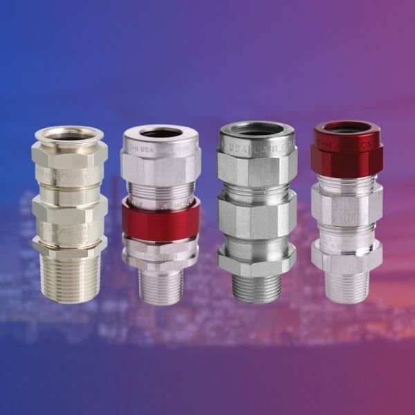
In hazardous industrial environments where flammable gases, vapors, or combustible dust particles are present, every component of an electrical system must meet stringent safety standards. Among these critical components, explosion proof cable glands serve as the first line of defense in preventing potentially catastrophic incidents.
Cable glands, also known as cable connectors or cable fittings, might seem like small components in the grand scheme of industrial installations. However, their role in maintaining the integrity of explosion-proof enclosures cannot be overstated. This comprehensive guide will explore the functions, types, and thread standards of explosion proof cable glands, helping you make informed decisions for your hazardous area applications.
What Are Explosion Proof Cable Glands?
Explosion proof cable glands are specialized cable entry devices designed to provide secure termination and sealing of cables entering electrical enclosures in hazardous locations. Unlike standard cable glands used in general industrial applications, explosion proof variants are engineered to:
- Prevent the transmission of internal explosions to the external atmosphere
- Maintain the ingress protection rating of the enclosure
- Provide strain relief and mechanical protection for cables
- Ensure continuous electrical bonding and earthing
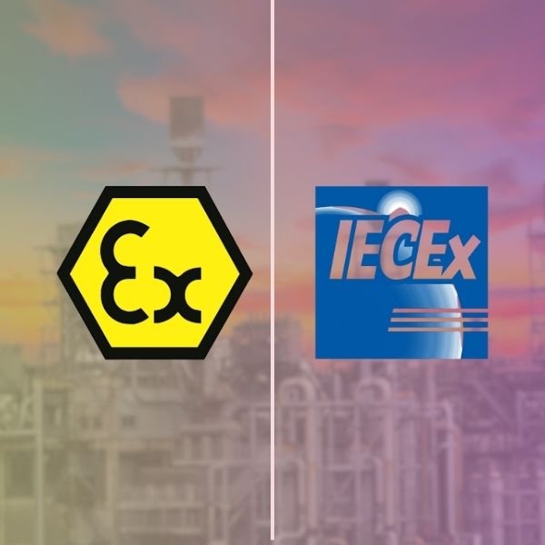
These devices are manufactured according to strict international standards such as IECEx, ATEX, UL, and CSA, ensuring they meet the rigorous requirements for use in potentially explosive atmospheres.
Primary Functions of Explosion Proof Cable Glands
1. Flameproof Barrier Creation
The most critical function of an explosion proof cable gland is creating a flameproof barrier between the internal enclosure and the external hazardous atmosphere. If an internal ignition occurs within the enclosure, the cable gland must prevent flames, hot gases, or sparks from escaping and igniting the surrounding explosive atmosphere.
This is achieved through precisely engineered flame paths – narrow gaps with specific lengths that cool any escaping gases below their ignition temperature before they reach the external environment.
2. Cable Sealing and Environmental Protection
Explosion proof cable glands provide hermetic sealing around cables, preventing:
- Ingress of moisture, dust, and contaminants
- Entry of hazardous gases into the enclosure
- Migration of gases along the cable cores (inner sealing)
High-quality cable glands achieve IP66, IP67, or even IP68 ratings, ensuring complete protection against water and dust ingress.
3. Mechanical Cable Retention
These devices secure cables firmly in place, preventing:
- Cable pullout due to tension or vibration
- Damage from mechanical stress
- Movement that could compromise electrical connections
The clamping mechanism distributes pressure evenly around the cable circumference, providing reliable strain relief without damaging the cable sheath.
4. Electrical Continuity and Earthing
Explosion proof cable glands maintain electrical continuity between the cable armor (for armored cables) and the enclosure. This earthing function is essential for:
- Personnel safety
- Equipment protection
- Electromagnetic compatibility (EMC)
- Fault current dissipation
5. Maintaining Enclosure Integrity
By providing a certified entry point, explosion proof cable glands ensure the overall explosion-proof integrity of the enclosure is maintained. An improperly sealed cable entry would compromise the entire protection concept of the installation.
Types of Explosion Proof Cable Glands
A. Based on Cable Type
1. Armored Cable Glands
Designed for steel wire armored (SWA) or aluminum wire armored (AWA) cables commonly used in industrial installations. These glands feature:
- Armor clamping rings that grip and terminate the armor wires
- Inner and outer sealing elements
- Armor earthing continuity through metallic contact
Applications: Heavy industrial installations, outdoor cable runs, areas requiring additional mechanical protection.
2. Unarmored Cable Glands
Used for cables without metallic armor, including:
- Rubber-sheathed flexible cables
- PVC-sheathed cables
- Instrumentation cables
These glands rely on compression sealing against the cable outer sheath.
Applications: Indoor installations, control systems, instrumentation connections.
3. Braided Cable Glands
Specifically designed for cables with braided screens or shields, commonly found in:
- Data communication cables
- Instrumentation cables
- EMC-sensitive applications
These glands provide termination for the braided shield while maintaining explosion-proof integrity.
B. Based on Material Construction
1. Brass Cable Glands
Advantages:
- Excellent corrosion resistance
- Good electrical conductivity
- Cost-effective solution
- Suitable for most industrial environments
Finish options: Nickel-plated, chrome-plated, or natural brass
2. Stainless Steel Cable Glands
Advantages:
- Superior corrosion resistance
- Ideal for marine and offshore applications
- Resistant to harsh chemicals
- Higher mechanical strength
Common grades: 316L stainless steel for maximum corrosion resistance
3. Aluminum Cable Glands
Advantages:
- Lightweight construction
- Good corrosion resistance with anodized finish
- Cost-effective for large installations
4. Plastic/Polymer Cable Glands
Advantages:
- Excellent chemical resistance
- Non-conductive (useful in specific applications)
- Lightweight
Note: Limited availability in explosion-proof ratings due to material constraints.
C. Based on Protection Type
1. Flameproof (Ex d) Cable Glands
Designed for use with flameproof enclosures according to IEC 60079-1. These glands:
- Contain any internal explosion
- Prevent flame transmission through engineered flame paths
- Are the most robust type for high-risk applications
2. Increased Safety (Ex e) Cable Glands
Used with increased safety enclosures according to IEC 60079-7. Features include:
- Enhanced sealing to prevent ingress
- No sparking components
- Higher IP ratings
3. Dust Ignition Protected (Ex t) Cable Glands
Designed for areas with combustible dust hazards according to IEC 60079-31. These provide:
- Dust-tight sealing (IP6X rating)
- Prevention of dust accumulation that could cause overheating
Understanding Thread Standards: Metric, PG, and NPT
One of the most crucial considerations when selecting explosion proof cable glands is the thread type. The thread must match the enclosure entry thread perfectly to maintain the explosion-proof rating. Three main standards dominate the global market:
1. Metric Thread (M Thread)
Overview:
Metric threads are the international standard defined by ISO 68-1 and are increasingly becoming the preferred choice worldwide. The thread designation consists of the letter “M” followed by the nominal diameter in millimeters.
Common Sizes:
| Thread Size | Outer Diameter | Pitch | Typical Cable Range |
|---|---|---|---|
| M16 x 1.5 | 16mm | 1.5mm | 4-8mm |
| M20 x 1.5 | 20mm | 1.5mm | 6-12mm |
| M25 x 1.5 | 25mm | 1.5mm | 10-18mm |
| M32 x 1.5 | 32mm | 1.5mm | 15-25mm |
| M40 x 1.5 | 40mm | 1.5mm | 22-32mm |
| M50 x 1.5 | 50mm | 1.5mm | 30-42mm |
| M63 x 1.5 | 63mm | 1.5mm | 40-56mm |
| M75 x 1.5 | 75mm | 1.5mm | 55-68mm |
Characteristics:
- Thread angle: 60 degrees
- Thread form: Symmetrical V-thread
- Measurement system: Metric (millimeters)
Advantages:
- Universal international standard
- Wide availability globally
- Consistent specifications across manufacturers
- Preferred for European and Asian markets
Applications:
Metric threads are commonly used in:
- European installations
- Modern global projects
- Equipment manufactured to IEC/ATEX standards
- Offshore and marine applications
2. PG Thread (Panzergewinde)
Overview:
PG threads, also known as German steel conduit threads, were developed in Germany and were once the European standard before metric threads gained prominence. “Panzergewinde” translates to “armored thread” in German.
Common Sizes:
| Thread Size | Outer Diameter | Pitch | Typical Cable Range |
|---|---|---|---|
| PG7 | 12.5mm | 1.27mm | 3-6.5mm |
| PG9 | 15.2mm | 1.41mm | 4-8mm |
| PG11 | 18.6mm | 1.41mm | 5-10mm |
| PG13.5 | 20.4mm | 1.41mm | 6-12mm |
| PG16 | 22.5mm | 1.41mm | 10-14mm |
| PG21 | 28.3mm | 1.59mm | 13-18mm |
| PG29 | 37mm | 1.59mm | 18-25mm |
| PG36 | 47mm | 1.59mm | 22-32mm |
| PG42 | 54mm | 1.59mm | 30-38mm |
| PG48 | 59.3mm | 1.59mm | 34-44mm |
Characteristics:
- Thread angle: 80 degrees
- Thread form: Rounded profile
- Measurement system: The number does not directly correspond to the diameter
Important Note:
PG threads are now considered legacy specifications and are being phased out in favor of metric threads. DIN 40430, which defined PG threads, has been withdrawn. However, many existing installations still use PG threads, creating ongoing demand for replacement and maintenance parts.
Applications:
- Legacy European installations
- Older German-manufactured equipment
- Replacement and maintenance of existing systems
3. NPT Thread (National Pipe Thread)
Overview:
NPT threads are the American standard for pipe threads, defined by ANSI/ASME B1.20.1. These tapered threads are widely used in North America and are common in oil and gas, petrochemical, and industrial applications following American standards.
Common Sizes:
| Thread Size | Threads Per Inch | Outer Diameter | Typical Cable Range |
|---|---|---|---|
| 1/4″ NPT | 18 | 13.7mm | 3-6mm |
| 3/8″ NPT | 18 | 17.1mm | 5-9mm |
| 1/2″ NPT | 14 | 21.3mm | 8-14mm |
| 3/4″ NPT | 14 | 26.7mm | 12-20mm |
| 1″ NPT | 11.5 | 33.4mm | 18-26mm |
| 1-1/4″ NPT | 11.5 | 42.2mm | 24-34mm |
| 1-1/2″ NPT | 11.5 | 48.3mm | 30-42mm |
| 2″ NPT | 11.5 | 60.3mm | 40-54mm |
Characteristics:
- Thread angle: 60 degrees
- Thread form: Tapered (1:16 taper rate)
- Measurement system: Imperial (inches)
- Sealing method: Thread taper creates seal when tightened
Advantages:
- Self-sealing due to tapered design
- Standard in North American markets
- Required for UL/CSA certified installations
- Common in oil and gas industry globally
Applications:
- North American installations
- Oil and gas facilities worldwide
- Equipment manufactured to UL/FM standards
- Projects following NEC (National Electrical Code)
Thread Comparison and Selection Guide
Quick Comparison Table
| Feature | Metric (M) | PG | NPT |
|---|---|---|---|
| Thread Type | Parallel | Parallel | Tapered |
| Thread Angle | 60° | 80° | 60° |
| Primary Market | Global/Europe | Legacy Europe | North America |
| Current Standard | ISO 68-1 | Withdrawn (DIN 40430) | ANSI/ASME B1.20.1 |
| Sealing Method | Washer/O-ring | Washer/O-ring | Thread tape/compound + washer |
| Future Availability | Excellent | Declining | Good |
Selection Criteria
Choose Metric Thread When:
- Designing new installations
- Working with IEC/ATEX certified equipment
- Requiring maximum global compatibility
- Following European or international standards
Choose PG Thread When:
- Maintaining existing installations with PG entries
- Replacing components in legacy systems
- Working with older European equipment
Choose NPT Thread When:
- Installing in North American facilities
- Following UL, FM, or CSA requirements
- Working in oil and gas per API standards
- Equipment specifies NPT entries
Key Considerations for Selection
1. Hazardous Area Classification
Understand your area classification:
- Zone 0, 1, 2 (Gas) or Zone 20, 21, 22 (Dust) per IEC
- Division 1 or 2 per NEC
- Class I, II, or III per NEC
2. Cable Specifications
Consider your cable details:
- Outer diameter range
- Armored or unarmored
- Number of cables (for multi-cable glands)
- Cable material and flexibility
3. Environmental Conditions
Evaluate the installation environment:
- Temperature range
- Corrosive substances
- UV exposure
- Vibration levels
4. Certification Requirements
Ensure compliance with:
- ATEX (European Union)
- IECEx (International)
- UL/FM (North America)
- Other regional certifications
5. Ingress Protection
Select appropriate IP rating:
- IP66 for powerful water jets
- IP67 for temporary immersion
- IP68 for continuous immersion
Installation Best Practices
Pre-Installation Checklist
- ✅ Verify cable gland certification matches the area classification
- ✅ Confirm thread type matches enclosure entry
- ✅ Check cable diameter falls within the gland’s sealing range
- ✅ Inspect all components for damage
- ✅ Ensure proper tools are available
Installation Steps
- Prepare the cable: Strip outer sheath to required length; prepare armor if applicable
- Thread the components: Slide gland components onto the cable in correct sequence
- Insert into enclosure: Hand-tighten the gland into the enclosure entry
- Seal the cable: Tighten the sealing nut to compress the seal around the cable
- Secure the armor: For armored cables, ensure armor is properly clamped and earthed
- Final tightening: Use appropriate tools to achieve specified torque values
- Inspection: Verify all components are secure and sealing is complete
Common Installation Mistakes to Avoid
- ❌ Over-tightening, which can damage seals or cable
- ❌ Under-tightening, which compromises the seal
- ❌ Using incorrect cable size for the gland
- ❌ Failing to use proper sealing washers
- ❌ Mixing components from different manufacturers
- ❌ Ignoring torque specifications
Maintenance and Inspection
Regular Inspection Points
- Visual inspection: Check for corrosion, damage, or loosening
- Seal integrity: Verify no signs of moisture ingress
- Cable condition: Inspect for damage at the entry point
- Tightness: Confirm all connections remain secure
- Earthing: Test continuity for armored cable glands
Replacement Indicators
Replace cable glands when:
- Visible corrosion compromises the flameproof path
- Seals show signs of degradation
- Thread damage is observed
- Cable size changes require different gland
- Certification requirements change
Conclusion
Explosion proof cable glands are indispensable components in hazardous area electrical installations. Understanding their functions—from creating flameproof barriers to providing mechanical protection and electrical continuity—is essential for designing safe and compliant systems.
The choice between Metric, PG, and NPT thread standards depends primarily on the enclosure specifications, regional requirements, and applicable certifications. While Metric threads represent the modern international standard, NPT remains dominant in North American markets, and PG threads continue to be necessary for legacy system maintenance.
When selecting explosion proof cable glands, always prioritize:
- Proper certification for your hazardous area classification
- Correct thread type matching your enclosure
- Appropriate cable range for your installation
- Material suitability for your environmental conditions
By following proper selection criteria, installation practices, and maintenance procedures, explosion proof cable glands will provide reliable service and contribute to the overall safety of your hazardous area installations for years to come.