The explosion protection industry speaks its own language. Terms like “MESG,” “EPL,” “intrinsically safe,” and “Zone 0” form the foundation of technical specifications, certificates, and safety standards. Without understanding this specialized vocabulary, navigating hazardous area requirements becomes nearly impossible.
This comprehensive glossary provides detailed definitions, extensive comparison tables, and practical cross-references for over 100 essential terms. Whether you’re reviewing equipment certificates, writing specifications, or conducting safety audits, these tables and definitions will serve as your complete reference guide.
📚 How to Use This Glossary
Symbol/Format Meaning Bold text Main glossary entry Italic text Cross-reference to another term [Standard] Source standard reference 📌 Critical safety information ⚠️ Common mistakes or warnings ✅ Best practice or recommendation
A
AIT (Auto-Ignition Temperature) Aspect Details Definition Minimum temperature at which a substance spontaneously ignites in air without external ignition source Also Known As Self-Ignition Temperature, Spontaneous Ignition Temperature Significance Determines required Temperature Class for equipment Units °C or °F Safety Rule Equipment max surface temp must be below AIT Standard [IEC 60079-20-1]
Common Substance AIT Values
Substance AIT (°C) AIT (°F) Min T-Class Required Carbon Disulfide 95 203 T6 Diethyl Ether 160 320 T4 Diesel 225 437 T3 Gasoline 280 536 T3 Ethanol 363 685 T2 Ethylene 425 797 T2 Propane 450 842 T2 Methane 595 1103 T1 Hydrogen 560 1040 T1 Ammonia 630 1166 T1
Ambient Temperature (Tamb) Parameter Specification Definition Temperature of air/environment surrounding equipment Standard Range -20°C to +40°C Extended Range -60°C to +70°C (special applications) Impact on T-Class Higher ambient = higher surface temperature Marking Example “Tamb: -40°C to +60°C”
Ambient Temperature Derating Table
Rated T-Class at 40°C Actual Surface Temp at Different Ambients -20°C 0°C 20°C 40°C 60°C T3 (200°C) 140°C 160°C 180°C 200°C 220°C⚠️ T4 (135°C) 75°C 95°C 115°C 135°C 155°C⚠️ T5 (100°C) 40°C 60°C 80°C 100°C 120°C⚠️ T6 (85°C) 25°C 45°C 65°C 85°C 105°C⚠️
⚠️ = Exceeds rated T-class at elevated ambient
ATEX (ATmosphères EXplosibles) Component Details Type European Union Directives Equipment Directive 2014/34/EU Workplace Directive 1999/92/EC Scope Mandatory in EU member states Standards Base EN 60079 series (harmonized IEC) Certificate Format ATEX [Body] YY ATEX XXXX [X]
ATEX Marking Structure
Element Example Meaning CE Mark CE European conformity Ex Symbol ⟨Ex⟩ ATEX explosion protection Equipment Group II Surface industries Category 2 High protection (Zone 1) Atmosphere G Gas atmosphere Notified Body 0123 Certifying organization ID
Area Classification Aspect Description Purpose Systematically identify and categorize explosive atmosphere risks Process Owner Qualified hazardous area engineer Input Data Material properties, release sources, ventilation Output Documents Classification drawings, equipment schedules Review Frequency Initial + after modifications + periodic (3-5 years)
Area Classification Standards
Region/Industry Standard Application International Gas IEC 60079-10-1 Gases and vapors International Dust IEC 60079-10-2 Combustible dusts USA Petroleum API RP 500 Class/Division system USA Petroleum API RP 505 Zone system Europe EN 60079-10-1/2 ATEX compliance UK Model Code EI 15 Petroleum installations
B
Bonding Bonding vs Grounding Definition Purpose Bonding Connecting objects to each other Equalize electrical potential Grounding/Earthing Connecting objects to earth Dissipate charges to ground
Bonding Requirements by Application
Application Resistance Requirement Method Verification Tank-to-tank transfer < 10 ohms Bonding cable with clamps Before each transfer Pipe flanges < 10 ohms Bonding strap across gasket During installation Portable containers < 10^6 ohms Conductive hose or cable Visual + resistance test Rail car loading < 10 ohms Grounding clamp with interlock Automatic verification
C
Category (Equipment Category) Gas Equipment Categories
Category Protection Level Zone Suitability Fault Tolerance ATEX Marking 1G Very High Zone 0, 1, 2 2 faults II 1 G 2G High Zone 1, 2 1 fault II 2 G 3G Normal Zone 2 only Normal operation II 3 G
Dust Equipment Categories
Category Protection Level Zone Suitability Fault Tolerance ATEX Marking 1D Very High Zone 20, 21, 22 2 faults II 1 D 2D High Zone 21, 22 1 fault II 2 D 3D Normal Zone 22 only Normal operation II 3 D
CE Mark Requirements for Ex Equipment Component Required For Location on Equipment CE Symbol All EU products Visible on nameplate ⟨Ex⟩ Hexagon ATEX equipment Adjacent to CE mark Notified Body Number Category 1 & 2 Below CE mark Equipment Code All Ex equipment Below symbols
Certificates – Types and Purposes Certificate Type Issued By Purpose Validity Type-Examination Certificate Notified Body/ExCB Confirms design compliance While design unchanged Certificate of Conformity (CoC) Manufacturer Declares unit compliance Per unit/batch QAR (Quality Assessment Report) IECEx QAB Verifies quality system 3 years + surveillance CoPC (Personnel Competence) IECEx CoPC Body Individual competency 3 years Unit Verification Certificate Notified Body Single unit compliance Specific unit only
Class (NEC Classification) Class Hazardous Material Typical Substances IEC Equivalent Class I Flammable gases/vapors Methane, gasoline, hydrogen Zone 0, 1, 2 Class II Combustible dusts Flour, coal, metal powders Zone 20, 21, 22 Class III Ignitable fibers/flyings Cotton, wood shavings Zone 20, 21, 22 (partial)
Combustible Dust Properties Property Definition Typical Values Test Standard Particle Size Maximum diameter < 500 μm Sieve analysis MIE (Minimum Ignition Energy) Energy to ignite cloud 1-1000 mJ IEC 61241-2-3 MIT (Minimum Ignition Temp) – Cloud Cloud auto-ignition 300-600°C IEC 61241-2-1 MIT – Layer 5mm layer ignition 200-400°C IEC 61241-2-1 Kst Value Explosion severity 0-300+ bar·m/s IEC 61241-2-1 Pmax Maximum pressure 5-12 bar IEC 61241-2-1 LEL Lower Explosive Limit 15-500 g/m³ Various
Common Dust Explosion Parameters
Material St Class Kst (bar·m/s) MIE (mJ) MIT-Cloud (°C) MIT-Layer (°C) Aluminum St 3 >300 10-50 590 450 Coal St 1 100-150 30-100 500-600 180-250 Flour St 1 100-150 30-100 400-500 340-360 Sugar St 1-2 150-200 10-30 350-400 400-460 Wood St 1 100-200 20-40 400-500 260-300 Polyethylene St 1 100-150 10-30 400-450 320-350
D
Deflagration vs Detonation Parameter Deflagration Detonation Flame Speed Subsonic (<340 m/s) Supersonic (>1000 m/s) Pressure Ratio 8-10:1 20-40:1 Pressure Rise Rate Moderate Extremely rapid Damage Type Pressure/thermal Shock wave Ex Protection Standard Ex d suitable Special protection required Typical Substances Most hydrocarbons Acetylene, ethylene oxide
Division (NEC) vs Zone (IEC) Comparison NEC Division Condition Duration/Year IEC Zone Equivalent EPL Equivalent Division 1 Normal operation >10 hours Zone 0 + Zone 1 Ga + Gb Division 2 Abnormal only <10 hours Zone 2 Gc
Dust Layer Temperature Derating Dust Layer Thickness Temperature Derating Factor Example: Equipment at T3 (200°C) No dust 1.0 200°C safe < 5 mm 1.0 200°C safe 5 mm 0.75 150°C maximum 12.5 mm 0.5 100°C maximum > 50 mm Site specific Testing required
E
Encapsulation (Ex m) Protection Levels Level Symbol Zone Suitability Application Examples Key Requirements Level a ma Zone 0, 20 Sensors, small electronics 2 fault tolerance Level b mb Zone 1, 21 Solenoids, indicators 1 fault tolerance Level c mc Zone 2, 22 General electronics Normal operation
EPL (Equipment Protection Level) Complete Matrix Gas Equipment (G)
EPL Protection Level Zone Suitability Category Fault Tolerance Typical Protection Types Ga Very High 0, 1, 2 1G 2 faults ia, ma, da, s Gb High 1, 2 2G 1 fault d, e, ib, mb, o, p, q Gc Enhanced 2 only 3G Normal operation n, ic, mc, pz
Dust Equipment (D)
EPL Protection Level Zone Suitability Category Fault Tolerance Typical Protection Types Da Very High 20, 21, 22 1D 2 faults ia, ma, ta Db High 21, 22 2D 1 fault ib, mb, pb, tb Dc Enhanced 22 only 3D Normal operation ic, mc, pc, tc
Mining Equipment (M)
EPL Protection Level Application De-energization Ma Very High With methane present Remains energized Mb High Methane may appear De-energized when detected
Equipment Group Classification Group Application Subgroups Typical Hazards I Underground mining – Methane (firedamp) II Surface industries – Gas IIA, IIB, IIC Various gases/vapors III Surface industries – Dust IIIA, IIIB, IIIC Combustible dusts
Group II Gas Subgroups
Subgroup MESG Range MIC Ratio Representative Gases IIA >0.9 mm >0.8 Propane, Methane, Gasoline IIB 0.5-0.9 mm 0.45-0.8 Ethylene, H₂S IIC <0.5 mm <0.45 Hydrogen, Acetylene
Group III Dust Subgroups
Subgroup Material Type Electrical Conductivity Examples IIIA Combustible flyings/fibers Variable Cotton, rayon IIIB Non-conductive dust >10³ Ω·m Flour, wood, plastics IIIC Conductive dust <10³ Ω·m Aluminum, carbon
Explosive Atmosphere Requirements Element Requirement Typical Range Fuel Flammable gas/vapor/dust Various Oxygen Oxidizing agent 12-21% typical Concentration Between LEL and UEL Substance specific Temperature Below AIT Substance specific Pressure Near atmospheric 0.8-1.1 bar typical Confinement Some degree of enclosure Partial to complete
F
Fire Triangle & Tetrahedron Model Elements Prevention Strategy Fire Triangle Fuel + Oxygen + Heat Remove any one element Fire Tetrahedron Fuel + Oxygen + Heat + Chain Reaction Remove element or break chain
Prevention Methods by Element
Element Control Method Example Application Fuel Containment Sealed systems, leak detection Oxygen Inerting N₂ blanketing, CO₂ purge Heat/Ignition Ex equipment Flameproof, intrinsically safe Chain Reaction Suppression Halon, dry chemical
Flameproof (Ex d) Specifications Parameter IIA IIB IIC Min Flamepath Length 25 mm 25 mm 40 mm Max Gap (Cylindrical) 0.40 mm 0.20 mm 0.10 mm Max Gap (Plane) 0.30 mm 0.15 mm 0.08 mm Min Wall Thickness Design dependent Design dependent Design dependent Typical Test Pressure 1.5 × Pmax 1.5 × Pmax 1.5 × Pmax
Flameproof Protection Levels
Level Symbol Zone Suitability Application Level a da Zone 0 (rare) Special applications Level b db Zone 1, 2 Standard industrial Level c dc Zone 2 only Light duty
Flash Point Classification Classification Flash Point Range Examples Hazard Level Extremely Flammable < 0°C Gasoline (-43°C), Acetone (-20°C) Very High Highly Flammable 0-21°C Ethanol (13°C), MEK (−9°C) High Flammable 21-55°C Diesel (52°C), Kerosene (38°C) Moderate Combustible 55-93°C Fuel Oil (69°C) Low Non-Flammable > 93°C Motor Oil (>150°C) Minimal
G
Gas Group Detailed Properties Gas/Vapor Gas Group MESG (mm) MIC Ratio AIT (°C) LEL (%) UEL (%) Required T-Class Acetone IIA 1.04 0.88 465 2.5 13.0 T1 Acetylene IIC 0.37 0.17 305 2.5 81.0 T2 Ammonia IIA 3.17 0.89 630 15.0 28.0 T1 Benzene IIA 0.99 0.88 498 1.2 8.0 T1 Butane IIA 0.98 0.82 365 1.8 8.4 T2 Carbon Disulfide IIC 0.34 0.29 95 1.0 50.0 T6 Carbon Monoxide IIB 0.84 0.65 605 12.5 74.0 T1 Diesel IIA ~1.0 ~0.85 225 0.6 6.5 T3 Diethyl Ether IIB 0.87 0.54 160 1.9 36.0 T4 Ethanol IIB 0.89 0.79 363 3.3 19.0 T2 Ethylene IIB 0.65 0.66 425 2.7 36.0 T2 Gasoline IIA 0.91 0.82 280 1.4 7.6 T3 Hexane IIA 0.93 0.88 225 1.1 7.5 T3 Hydrogen IIC 0.29 0.21 560 4.0 75.0 T1 Hydrogen Sulfide IIB 0.71 0.66 260 4.0 44.0 T3 Methane IIA 1.14 1.00 595 5.0 15.0 T1 Methanol IIA 0.92 0.89 385 6.0 36.0 T2 Propane IIA 0.92 0.82 450 2.1 9.5 T2 Toluene IIA 1.00 0.88 480 1.1 7.1 T1
Grounding System Requirements Application Max Resistance Test Frequency Standard Fixed Equipment <10 Ω Annual IEC 60079-14 Portable Equipment <10⁶ Ω Before use NFPA 77 Tank Trucks <10 Ω Each loading API RP 2003 Personnel (conductive shoes) <10⁸ Ω Monthly IEC 61340-4-3 Flooring (dissipative) 10⁴-10⁸ Ω Annual IEC 61340-4-1
H-I
Hazardous Area Zone Comparison Gas/Vapor Zones
Zone Explosive Atmosphere Presence Duration/Year Typical Locations Zone 0 Continuous/long periods >1000 hours Inside tanks, vessels Zone 1 Likely during normal operation 10-1000 hours Near vents, seals, sampling Zone 2 Not likely, abnormal only <10 hours Adjacent to Zone 1, flanges
Dust Zones
Zone Dust Cloud Presence Typical Locations Zone 20 Continuous Inside hoppers, silos Zone 21 Likely during operation Filling/discharge points Zone 22 Unlikely, abnormal only Storage areas
Hot Work Permit Requirements Requirement Description Verification Method Gas Testing LEL <10% typical Calibrated gas detector Isolation Physical/energy isolation Lockout/tagout Ventilation Forced air if required Air flow measurement Fire Watch Trained personnel present Named individual Fire Equipment Appropriate extinguishers Visual inspection Time Limit Typically 8 hours max Permit expiry time Authorization Multiple signatures Area owner, safety, operations
IECEx System Components Component Function Participants ExCB Certification Bodies 50+ organizations globally ExTL Testing Laboratories 60+ laboratories Member Countries Recognition/acceptance 35+ countries CoPC Scheme Personnel competence 10,000+ certified individuals Equipment Scheme Product certification 40,000+ certificates Service Facility Repair/overhaul certification Growing program
IECEx vs ATEX Comparison
Aspect IECEx ATEX Geographic Scope Global (35+ countries) EU mandatory Standards IEC 60079 (pure) EN 60079 (harmonized IEC) Legal Status Voluntary certification EU legal requirement QA Requirements QAR mandatory Module compliance Certificate Format IECEx XXX YY.NNNN ATEX NNNN Marking IECEx logo CE + ⟨Ex⟩
Ignition Source Categories Category Examples Control Methods Electrical Sparks, arcs, hot surfaces Ex-rated equipment Mechanical Friction, impact sparks Non-sparking tools Thermal Hot surfaces, exhaust Temperature limiting Chemical Exothermic reactions Process control Static Electrostatic discharge Bonding/grounding Lightning Direct/indirect strikes Lightning protection RF/EM Radio waves, microwaves Power limiting Ultrasonic High-frequency vibration Rare, special assessment
Increased Safety (Ex e) Requirements Parameter Standard Equipment Ex e Requirement Improvement Factor Clearance Distance X mm 1.5X mm minimum 50% increase Creepage Distance Y mm 1.5Y mm minimum 50% increase Temperature Rise 100°C typical 80°C maximum 20% reduction Terminal Quality Standard Anti-loosening Enhanced IP Rating IP44 typical IP54 minimum Higher ingress protection Impact Resistance Standard 7J minimum Impact test required
Intrinsically Safe (Ex i) System Parameters Level Symbol Zone Fault Tolerance Cable Faults Component Faults ia Ex ia 0, 1, 2 2 countable faults 2 2 ib Ex ib 1, 2 1 countable fault 1 1 ic Ex ic 2 Normal operation 0 0
IS System Components
Component Location Function Certification IS Equipment Hazardous area Field device Ex ia/ib/ic certified Associated Apparatus Safe area Energy limiting [Ex ia/ib/ic] certified IS Cable Between areas Signal transmission Parameters specified Earth/Ground Throughout Reference potential <1Ω typical
IP Rating Detailed Matrix First Digit – Solids Protection
Digit Protection Against Effective Against 0 No protection – 1 Objects >50mm Back of hand 2 Objects >12.5mm Fingers 3 Objects >2.5mm Tools 4 Objects >1mm Wires 5 Dust protected Limited dust ingress 6 Dust tight No dust ingress
Second Digit – Liquids Protection
Digit Protection Against Test Details 0 No protection – 1 Dripping water Vertical drops 2 Dripping water tilted 15° 15° tilt 3 Spraying water 60° from vertical 4 Splashing water All directions 5 Water jets 6.3mm nozzle 6 Powerful water jets 12.5mm nozzle 7 Temporary immersion 1m for 30 min 8 Continuous immersion Specified depth
K-N
Kst Value and Dust Classification St Class Kst Range (bar·m/s) Explosion Characteristic Examples St 0 0 No explosion Inert materials St 1 1-200 Weak explosion Flour, coal, wood St 2 201-300 Strong explosion Organic pigments, resins St 3 >300 Very strong explosion Aluminum, magnesium
LEL/UEL Common Values Substance LEL (% vol) UEL (% vol) Range Width Danger Level Acetylene 2.5 81.0 78.5% Extremely wide Hydrogen 4.0 75.0 71.0% Very wide Methane 5.0 15.0 10.0% Moderate Propane 2.1 9.5 7.4% Moderate Gasoline 1.4 7.6 6.2% Moderate Ammonia 15.0 28.0 13.0% Narrow
MESG Values and Gas Groups Gas MESG (mm) Gas Group Gap Design Impact Hydrogen 0.29 IIC Requires 0.1mm max gap Acetylene 0.37 IIC Requires 0.1mm max gap Ethylene 0.65 IIB Requires 0.2mm max gap Propane 0.92 IIA Allows 0.4mm gap Methane 1.14 IIA Allows 0.4mm gap
NEC vs IEC Classification Comparison Gas/Vapor Classification
NEC System IEC System Probability Duration/Year Class I, Division 1, Group A Zone 0/1, IIC (Acetylene) Normal >10 hours Class I, Division 1, Group B Zone 0/1, IIC (Hydrogen) Normal >10 hours Class I, Division 1, Group C Zone 0/1, IIB (Ethylene) Normal >10 hours Class I, Division 1, Group D Zone 0/1, IIA (Methane) Normal >10 hours Class I, Division 2, Groups A-D Zone 2, IIA/IIB/IIC Abnormal <10 hours
Dust Classification
NEC System IEC System Material Type Class II, Division 1, Group E Zone 20/21, IIIC Metal dust (conductive) Class II, Division 1, Group F Zone 20/21, IIIB Carbon dust Class II, Division 1, Group G Zone 20/21, IIIB Non-conductive dust Class II, Division 2, Groups E-G Zone 22, IIIA/B/C All dusts – abnormal
Non-Sparking (Ex n) Subtypes Subtype Full Name Application Zone nA Non-sparking General equipment 2 nC Sparking equipment enclosed Contactors, relays 2 nR Restricted breathing Limited gas exchange 2 nL Energy limited Low power circuits 2 nP Simplified pressurization Small enclosures 2 nZ Type n with Zone 0 equipment Combination protection 2
O-R
Oil Immersion (Ex o) Specifications Parameter Requirement Test Method Oil Level >25mm above components Visual inspection Oil Type Mineral/synthetic specified Manufacturer spec Flash Point >200°C typical ASTM D92 Dielectric Strength >30 kV minimum IEC 60156 Moisture Content <50 ppm Karl Fischer Maintenance Annual oil analysis Laboratory testing
Pressurization (Ex p) Types Type Symbol Source of Release Inside Zone Reduction Application px Ex px No release Zone 1 → Non-hazardous Large motors py Ex py Limited release possible Zone 1 → Zone 2 Analyzer houses pz Ex pz No release Zone 2 → Non-hazardous Control panels
Pressurization System Requirements
Component Function Typical Specification Purge Volume 5 × enclosure volume Before energization Minimum Pressure 25 Pa (0.1″ H₂O) During operation Pressure Alarm <25 Pa Warning signal Pressure Trip <12.5 Pa Equipment shutdown Door Interlock Pressure loss on opening Immediate shutdown
Protection Type Summary Matrix Type Name Principle Gas Zones Dust Zones Typical Power d Flameproof Containment 1, 2 – Unlimited e Increased Safety Prevention 1, 2 – Unlimited i Intrinsic Safety Energy limiting 0, 1, 2 20, 21, 22 <2W typical p Pressurization Exclusion 1, 2 21, 22 Unlimited m Encapsulation Isolation 0, 1, 2 20, 21, 22 Limited o Oil Immersion Isolation 1, 2 – High q Powder Filling Quenching 1, 2 – Limited n Non-Sparking Various 2 – Unlimited t Dust Protection Enclosure – 20, 21, 22 Unlimited
S-Z
Static Electricity Control Methods Method Application Specification Test Frequency Bonding Equipment to equipment <10 Ω Installation Grounding Equipment to earth <10 Ω Annual Conductive Flooring Personnel grounding <10⁶ Ω Annual Dissipative Flooring Static control 10⁶-10⁸ Ω Annual Humidity Control General area >50% RH Continuous Ionization Specific processes Balanced bipolar Quarterly Conductive Containers Portable equipment <10⁶ Ω Before use
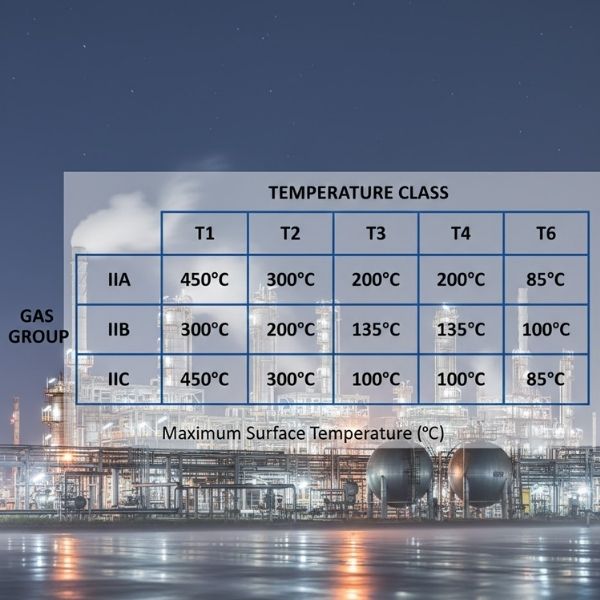
Temperature Class Comprehensive Table T-Class Max Surface °C Max Surface °F Common Substances Within Limit Safety Margin to AIT T1 450 842 Hydrogen (560°C), Methane (595°C), Ammonia (630°C) >100°C T2 300 572 Ethylene (425°C), Propane (450°C), Acetylene (305°C) >100°C T2A 280 536 – – T2B 260 500 – – T2C 230 446 – – T2D 215 419 – – T3 200 392 Gasoline (280°C), Jet Fuel (210°C), Diesel (225°C) >80°C T3A 180 356 – – T3B 165 329 – – T3C 160 320 – – T4 135 275 Diethyl Ether (160°C), Acetaldehyde (140°C) >25°C T4A 120 248 – – T5 100 212 – >20°C T6 85 185 Carbon Disulfide (95°C) >10°C
Type-Examination Certificate Contents Section Information Included Header Certificate number, issue date Applicant Manufacturer details Product Model, type, description Standards Applicable standards list Marking Ex marking requirements Test Reports Reference numbers Special Conditions If suffix ‘X’ or ‘U’ Drawings Assembly, dimensions Parameters Electrical ratings QA Requirements Manufacturing controls
Ventilation Impact on Zone Classification Ventilation Type Effectiveness Reliability Zone Impact High (VH) Very good Very reliable Can eliminate zones Medium (VM) Good Reliable Reduces zone extent Low (VL) Poor Unreliable Minimal impact None – – Conservative zones
Ventilation Requirements by Zone
Zone Natural Ventilation Mechanical Ventilation Failure Impact Zone 0 Not sufficient Cannot eliminate N/A Zone 1 May reduce to Zone 2 May eliminate Becomes Zone 0/1 Zone 2 May eliminate Usually eliminates Becomes Zone 1
Zone Classification Decision Matrix Source Grade Ventilation Effectiveness Resulting Zone Continuous High Zone 0 (reduced extent) Continuous Medium Zone 0 Continuous Low Zone 0 (extended) Primary High Zone 2 or Non-hazardous Primary Medium Zone 1 Primary Low Zone 1 (extended) Secondary High Non-hazardous Secondary Medium Zone 2 Secondary Low Zone 2 (extended)
Quick Reference Tables
Protection Type Selection by Zone Gas Zones
Zone Suitable Protection Types EPL Required Zone 0 ia, ma, da (rare), s Ga Zone 1 All Zone 0 + d, e, ib, mb, o, p, q Gb or Ga Zone 2 All Zone 0/1 + n, ic, mc Gc, Gb, or Ga
Dust Zones
Zone Suitable Protection Types EPL Required Zone 20 ia, ma, ta Da Zone 21 All Zone 20 + ib, mb, pb, tb Db or Da Zone 22 All Zone 20/21 + ic, mc, pc, tc Dc, Db, or Da
Certification Scheme Comparison Aspect ATEX IECEx NEC/UL/FM NEPSI KOSHA Region EU Global North America China Korea Mandatory Yes (EU) No Yes (USA/Canada) Yes (China) Yes (Korea) Standards EN 60079 IEC 60079 UL/FM/ANSI GB 3836 KS C IEC Recognition EU + others 35+ countries Americas China Korea Certificate Format ATEX NNNN IECEx XXX YY.NNNN Various GYB NNNNNN NNNN-ABO-NNNN
Common Equipment Applications Equipment Type Typical Zones Common Protection Types Special Considerations Motors 1, 2 d, e, p, n Bearing temperature monitoring Lighting 1, 2 d, e, n LED technology common Junction Boxes 0, 1, 2 e, d, ia Terminal quality critical Sensors 0, 1, 2 ia, d, m Often intrinsically safe Switches 1, 2 d, m Contacts must be protected Control Panels 2 p, n Often pressurized Portable Devices 0, 1, 2 ia, s Battery considerations Valves/Actuators 1, 2 d, m, e Solenoids often Ex m
Inspection Types and Frequencies Inspection Type Grade Frequency Scope Documentation Initial Detailed Before commissioning 100% equipment Full report Periodic Close/Visual As per schedule Sample/All Inspection sheets Sample Detailed 3-yearly typical 10-20% equipment Detailed report Continuous Visual Ongoing by operators Obvious defects Logbook
Inspection Grade Definitions
Grade Symbol Checks Performed Tools Required Visual V External defects visible Eyes only Close C Uses tools to access Basic tools Detailed D Opens enclosures Full toolkit + testing
Conversion Tables
Pressure Units From/To Pa mbar psi bar 1 Pa 1 0.01 0.000145 0.00001 1 mbar 100 1 0.0145 0.001 1 psi 6895 68.95 1 0.0689 1 bar 100,000 1000 14.5 1
Temperature Conversion Formula Conversion °C to °F °F = (°C × 9/5) + 32 °F to °C °C = (°F – 32) × 5/9 °C to K K = °C + 273.15
Distance/Area Coverage Measurement Metric Imperial Zone extent typical 1-3 meters 3-10 feet Flamepath length 25-40 mm 1-1.6 inches Gap tolerance 0.1-0.4 mm 0.004-0.016 inches
Conclusion
This comprehensive glossary with detailed tables provides the essential reference material for anyone working with explosion-protected equipment and hazardous area classification. The tabular format allows quick lookup of specifications, comparisons, and requirements across different standards and certification schemes.
Key Points to Remember:
Standards Harmonization: While ATEX, IECEx, and NEC use different terminology, the underlying safety principles are similarZone Determines Equipment: Always match equipment EPL/Category to zone requirementsMultiple Parameters: Gas group, temperature class, and protection type must ALL be appropriateDocumentation: Maintain certificates, inspection records, and classification drawingsCompetence: Use qualified personnel for design, installation, and maintenance
This glossary should be used in conjunction with:
Current versions of relevant standards
Manufacturer instructions
Local regulations
Site-specific risk assessments
For the most current information, always refer to the latest editions of IEC 60079, EN 60079, or applicable national standards.