Walk through any oil refinery, chemical plant, or offshore platform, and you’ll notice something peculiar on almost every piece of electrical equipment: a distinctive marking starting with “Ex” followed by a string of letters, numbers, and symbols that look like an encrypted code.
For those unfamiliar, labels like “Ex db IIC T4 Gb” or “② Ex ia IIC T6 Ga” might as well be hieroglyphics. Yet, these seemingly cryptic markings contain critical safety information. They tell engineers, inspectors, and workers exactly where the equipment can be safely installed and what hazards it can withstand.
Understanding Ex markings isn’t just for specialists—it’s essential knowledge for anyone working in or around hazardous areas. This article provides a complete, step-by-step guide to decoding every element of the Ex marking system.
What Does “Ex” Mean?
The “Ex” symbol is the internationally recognized prefix indicating that a piece of equipment is designed and certified for use in Explosive Atmospheres.
| Symbol | Meaning |
|---|---|
| Ex | Explosion protected equipment |
When you see “Ex” on equipment, it confirms that:
- The equipment has been specially designed to prevent ignition of surrounding explosive atmospheres
- It has been tested according to recognized international standards
- It has been certified by an accredited testing body
- It is suitable for use in classified hazardous areas (Zones 0, 1, 2, 20, 21, 22)
Without the Ex marking, standard electrical equipment is prohibited in hazardous areas because normal switches, motors, lights, and electronics can produce sparks or hot surfaces capable of igniting explosive gases or dusts.
The Anatomy of an Ex Marking
An Ex marking contains multiple elements, each providing specific information. Let’s break down a typical marking:
Example Marking:
┌─────────────────────────────────────────────────────────┐
│                                                         │
│     II 2 G     Ex  db  IIB  T4  Gb                      │
│     ─┬─┬─┬─    ─┬─ ─┬─ ─┬── ─┬─ ─┬─                     │
│      │ │ │      │   │   │    │   │                      │
│      │ │ │      │   │   │    │   └── Equipment          │
│      │ │ │      │   │   │    │       Protection Level   │
│      │ │ │      │   │   │    │                          │
│      │ │ │      │   │   │    └────── Temperature Class  │
│      │ │ │      │   │   │                               │
│      │ │ │      │   │   └────────── Gas Group           │
│      │ │ │      │   │                                   │
│      │ │ │      │   └────────────── Protection Type     │
│      │ │ │      │                                       │
│      │ │ │      └────────────────── Ex Symbol           │
│      │ │ │                                              │
│      │ │ └───────────────────────── Atmosphere Type     │
│      │ │                            (G=Gas, D=Dust)     │
│      │ │                                                │
│      │ └─────────────────────────── Equipment Category  │
│      │                              (1, 2, or 3)        │
│      │                                                  │
│      └───────────────────────────── Equipment Group     │
│                                     (I, II, or III)     │
│                                                         │
└─────────────────────────────────────────────────────────┘
Let’s decode each element systematically.
Element 1: Equipment Group (I, II, III)
The Equipment Group indicates the general application environment:
| Group | Application | Examples |
|---|---|---|
| I | Mining (underground coal mines with firedamp) | Methane in coal mines |
| II | Surface industries (gases and vapors) | Refineries, chemical plants, fuel stations |
| III | Surface industries (combustible dusts) | Flour mills, grain silos, pharmaceutical plants |
Note: Group II is the most common in general industry and is further subdivided into IIA, IIB, and IIC based on gas properties.
Element 2: Equipment Category (1, 2, 3)
The Equipment Category indicates the level of protection and the zones where equipment can be installed:
For Gas Atmospheres (G):
| Category | Protection Level | Suitable Zones | Description |
|---|---|---|---|
| 1G | Very High | Zone 0, 1, 2 | Remains safe even with two faults |
| 2G | High | Zone 1, 2 | Remains safe with one expected fault |
| 3G | Normal | Zone 2 only | Safe during normal operation |
For Dust Atmospheres (D):
| Category | Protection Level | Suitable Zones | Description |
|---|---|---|---|
| 1D | Very High | Zone 20, 21, 22 | Remains safe even with two faults |
| 2D | High | Zone 21, 22 | Remains safe with one expected fault |
| 3D | Normal | Zone 22 only | Safe during normal operation |
Visual Guide:
EQUIPMENT CATEGORY vs ZONE SUITABILITY

Category 1 ──── Zone 0/20 ───┐
      │                      │
      ├─────── Zone 1/21 ────┤
      │                      │
      └─────── Zone 2/22 ────┘

Category 2 ──── Zone 1/21 ───┐
      │                      │
      └─────── Zone 2/22 ────┘

Category 3 ──── Zone 2/22 ───┘
Element 3: Atmosphere Type (G or D)
This letter indicates what type of explosive atmosphere the equipment is designed for:
| Letter | Meaning | Hazardous Substance |
|---|---|---|
| G | Gas | Flammable gases and vapors |
| D | Dust | Combustible dusts |
Combined Marking: Some equipment is rated for both gases AND dusts. In this case, you’ll see both indicators:
II 2 GD Ex db tb IIIC T4 Gb DbElement 4: The “Ex” Symbol
The Ex symbol confirms the equipment is certified for explosive atmospheres. This is the universal identifier recognized worldwide.
In some regional markings, you may see variations:
| Marking | Meaning |
|---|---|
| Ex | IEC/International standard |
| EEx | Older European (pre-ATEX) notation—now obsolete |
| AEx | North American (NEC 505) notation |
Element 5: Protection Type (The Most Critical Element)
The Protection Type is arguably the most important part of the Ex marking. It describes the method used to prevent the equipment from igniting the surrounding explosive atmosphere.
Different protection methods work in fundamentally different ways, and each has specific applications, advantages, and limitations.
Complete Protection Type Table:
| Code | Name | Method | Typical Applications | Zone Suitability |
|---|---|---|---|---|
| d | Flameproof Enclosure | Contains explosion inside; prevents propagation | Motors, junction boxes, switches, lights | Zone 1, 2 |
| e | Increased Safety | Prevents sparks and hot surfaces from occurring | Terminal boxes, junction boxes, light fittings | Zone 1, 2 |
| i | Intrinsic Safety | Limits energy below ignition threshold | Sensors, transmitters, portable devices | Zone 0, 1, 2 |
| p | Pressurization/Purging | Maintains positive pressure with clean air/gas | Large motors, control panels, analyzers | Zone 1, 2 |
| m | Encapsulation | Components embedded in resin/compound | Small electronic components, solenoids | Zone 0, 1, 2 |
| o | Oil Immersion | Components submerged in protective oil | Transformers, switchgear | Zone 1, 2 |
| q | Powder/Sand Filling | Components surrounded by quartz powder | Capacitors, fuses | Zone 1, 2 |
| n | Non-Sparking | Normal operation doesn’t produce ignition | General equipment for Zone 2 | Zone 2 only |
| t | Protection by Enclosure (Dust) | Dust-tight enclosure prevents ingress | Equipment in dusty environments | Zone 20, 21, 22 |
| s | Special Protection | Non-standard methods, individually assessed | Unique applications | As certified |
Sub-Types and Levels:
Many protection types have subcategories indicating different levels of protection:
Intrinsic Safety (i):
| Code | Level | Zone Suitability |
|---|---|---|
| ia | Highest—safe with two faults | Zone 0, 1, 2 |
| ib | High—safe with one fault | Zone 1, 2 |
| ic | Normal—safe during normal operation | Zone 2 only |
Flameproof (d):
| Code | Level | Description |
|---|---|---|
| da | Highest | For Zone 0 (rare) |
| db | High | For Zone 1, 2 |
| dc | Normal | For Zone 2 only |
Encapsulation (m):
| Code | Level | Zone Suitability |
|---|---|---|
| ma | Highest | Zone 0, 1, 2 |
| mb | High | Zone 1, 2 |
| mc | Normal | Zone 2 only |
Non-Sparking (n):
| Code | Subtype | Description |
|---|---|---|
| nA | Non-sparking | General non-sparking equipment |
| nC | Sparking contacts in enclosure | Enclosed switches and relays |
| nR | Restricted breathing | Limited air exchange with atmosphere |
| nL | Energy limited | Similar to intrinsic safety concept |
Detailed Protection Type Explanations:
Ex d – Flameproof Enclosure
Concept: If an explosion occurs INSIDE the enclosure, the robust housing contains it and cools the escaping gases so they cannot ignite the external atmosphere.
FLAMEPROOF ENCLOSURE PRINCIPLE

    External Explosive           External Explosive
       Atmosphere                   Atmosphere
           ↓                            ↓
    ┌──────────────┐            ┌──────────────┐
    │   ┌──────┐   │            │              │
    │   │ BOOM │   │  ─────→    │   (Safe)     │
    │   └──────┘   │  Flame     │              │
    │   Internal   │  Cooled    │  No External │
    │   Explosion  │  via Gap   │  Ignition    │
    └──────────────┘            └──────────────┘

    Gap = MESG (Maximum Experimental Safe Gap)
Characteristics:
- Heavy, robust enclosures
- Machined flame paths with precise gap tolerances
- All openings (cable entries, covers) must maintain flameproof integrity
- Common for motors, junction boxes, lighting, switches
Example Marking: Ex db IIB T4 Gb
Ex e – Increased Safety
Concept: Prevents sparks, arcs, and excessive temperatures from occurring in the first place through enhanced design margins.
Characteristics:
- No sparking components allowed inside
- Increased clearances and creepage distances
- High-quality terminals and connections
- Cannot be used for switching devices
- Common for terminal/junction boxes and light fittings
Example Marking: Ex eb IIC T4 Gb
Ex i – Intrinsic Safety
Concept: Limits electrical and thermal energy in the circuit to levels below what’s required to ignite the most easily ignitable mixture.
INTRINSIC SAFETY PRINCIPLE

    Normal Circuit           Intrinsically Safe Circuit

    High Energy    ─────→    Low Energy
    (Can ignite)             (Cannot ignite)

    ┌─────────────┐          ┌─────────────┐
    │   Spark!    │          │   (spark)   │
    │   IGNITION  │          │   Too weak  │
    │             │          │  No ignition│
    └─────────────┘          └─────────────┘
Characteristics:
- Energy limited at source by barriers/isolators
- Lightweight, small equipment possible
- Live maintenance allowed in Zone 0 (for “ia”)
- Requires complete system certification (device + cable + barrier)
- Common for sensors, transmitters, portable devices
Example Marking: Ex ia IIC T4 Ga
Ex p – Pressurization/Purging
Concept: Maintains the interior of an enclosure at a pressure higher than the external atmosphere using clean air or inert gas, preventing hazardous gases from entering.
PRESSURIZATION PRINCIPLE

    Hazardous          ┌────────────────┐      Clean
    Atmosphere   ←──── │   POSITIVE     │ ←─── Air/Gas
    (Cannot enter)     │   PRESSURE     │      Supply
                       │   ENCLOSURE    │
                       └────────────────┘
Characteristics:
- Requires continuous air/gas supply
- Pre-purge cycle before energizing
- Interlock systems for pressure failure
- Allows use of non-Ex rated equipment inside
- Common for control rooms, large panels, analyzers
Example Marking: Ex pxb IIB T4 Gb
Ex m – Encapsulation
Concept: Electrical components are completely embedded in a compound (epoxy resin) that prevents contact with the explosive atmosphere.
Characteristics:
- Components cannot be accessed or repaired
- Compact design possible
- Robust protection against ingress
- Common for small electronics, solenoid valves, sensors
Example Marking: Ex ma IIC T4 Ga
Ex t – Protection by Enclosure (for Dust)
Concept: A dust-tight enclosure prevents combustible dust from entering and accumulating on hot surfaces.
Characteristics:
- High IP rating (typically IP6X)
- Surface temperature limited
- Common for all electrical equipment in dusty environments
Example Marking: Ex tb IIIC T85°C Db
Note for Dust: Temperature for dust equipment is often marked as actual temperature (e.g., T85°C) rather than T-class.
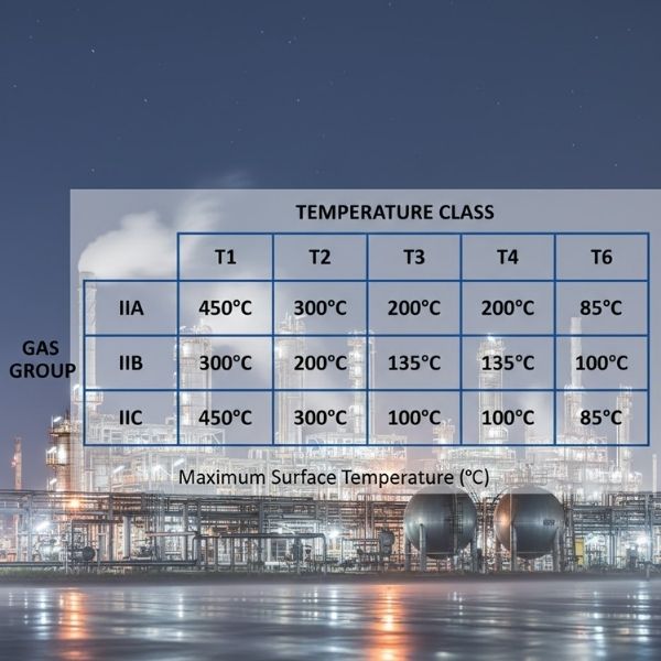
Element 6: Gas Group (IIA, IIB, IIC)
The Gas Group indicates which gases/vapors the equipment is certified to handle, based on their explosive characteristics (MESG and MIC ratio).
| Gas Group | Representative Gases | Danger Level |
|---|---|---|
| IIA | Methane, Propane, Gasoline, Acetone | Lowest |
| IIB | Ethylene, Hydrogen Sulfide, Diethyl Ether | Moderate |
| IIC | Hydrogen, Acetylene, Carbon Disulfide | Highest |
Hierarchy Rule:
Equipment rated for a higher group covers all lower groups:
| Equipment Rating | Suitable For |
|---|---|
| IIC | IIC, IIB, IIA |
| IIB | IIB, IIA |
| IIA | IIA only |
Element 7: Temperature Class (T1-T6)
The Temperature Class indicates the maximum surface temperature of the equipment during operation. This must be below the auto-ignition temperature of gases present.
| T-Class | Max Surface Temp | Suitable for Gases with AIT > |
|---|---|---|
| T1 | 450°C | 450°C |
| T2 | 300°C | 300°C |
| T3 | 200°C | 200°C |
| T4 | 135°C | 135°C |
| T5 | 100°C | 100°C |
| T6 | 85°C | 85°C |
Hierarchy Rule:
Lower T-classes (lower temperatures) cover higher ones:
| Equipment Rating | Suitable For |
|---|---|
| T6 | T6, T5, T4, T3, T2, T1 |
| T4 | T4, T3, T2, T1 |
| T1 | T1 only |
Element 8: Equipment Protection Level (EPL)
The Equipment Protection Level (EPL) provides a clear indication of the level of protection offered, relating directly to zone suitability.
For Gas (G):
| EPL | Protection Level | Zone Suitability |
|---|---|---|
| Ga | Very High | Zone 0, 1, 2 |
| Gb | High | Zone 1, 2 |
| Gc | Enhanced | Zone 2 only |
For Dust (D):
| EPL | Protection Level | Zone Suitability |
|---|---|---|
| Da | Very High | Zone 20, 21, 22 |
| Db | High | Zone 21, 22 |
| Dc | Enhanced | Zone 22 only |
Complete Marking Examples: Decoded
Example 1: Flameproof Motor
II 2 G Ex db IIB T4 Gb| Element | Value | Meaning |
|---|---|---|
| II | Equipment Group II | Surface industries |
| 2 | Category 2 | High protection level |
| G | Gas | For gas/vapor atmospheres |
| Ex | Explosion protected | Certified for hazardous areas |
| db | Flameproof (level b) | Contains internal explosion |
| IIB | Gas Group IIB | Suitable for IIB and IIA gases |
| T4 | Temperature Class T4 | Max surface temp 135°C |
| Gb | EPL Gb | Suitable for Zone 1 and 2 |
Plain English: This motor can be used in Zone 1 or Zone 2 areas containing gases like ethylene, hydrogen sulfide, or any IIA gases (methane, propane, gasoline), where the auto-ignition temperature exceeds 135°C.
Example 2: Intrinsically Safe Transmitter
I M1 Ex ia I Ma
II 1 G Ex ia IIC T4 Ga| Line 1 | Meaning |
|---|---|
| I M1 | Mining equipment, Category M1 (highest for mines) |
| Ex ia I Ma | Intrinsically safe, Group I, EPL Ma |
| Line 2 | Meaning |
|---|---|
| II 1 G | Group II, Category 1, Gas atmosphere |
| Ex ia IIC T4 Ga | Intrinsically safe (highest level), all gases, max 135°C, Zone 0/1/2 |
Plain English: This transmitter is dual-rated for underground mining AND surface industries. It can be used in the most dangerous Zone 0 locations with any gas including hydrogen.
Example 3: Increased Safety Junction Box
II 2 G Ex eb IIC T5 Gb| Element | Value | Meaning |
|---|---|---|
| II 2 G | Group II, Category 2, Gas | Surface industry, Zone 1/2 |
| Ex eb | Increased Safety (level b) | No sparking components, enhanced design |
| IIC | Gas Group IIC | All gases including hydrogen |
| T5 | Temperature Class T5 | Max surface temp 100°C |
| Gb | EPL Gb | Zone 1 and 2 |
Plain English: This junction box is suitable for Zone 1 and 2 areas with any gas group, but cannot be used where auto-ignition temperatures are below 100°C (e.g., Carbon Disulfide at 95°C requires T6).
Example 4: Dust-Protected Light Fixture
II 2 D Ex tb IIIC T80°C Db| Element | Value | Meaning |
|---|---|---|
| II 2 D | Group II, Category 2, Dust | Surface industry, dust atmosphere |
| Ex tb | Protection by enclosure (level b) | Dust-tight enclosure |
| IIIC | Dust Group IIIC | Conductive dusts (e.g., aluminum) |
| T80°C | Temperature | Max surface temp 80°C |
| Db | EPL Db | Zone 21 and 22 |
Plain English: This light fixture is dust-tight and suitable for Zone 21 and 22 areas with conductive dusts. Maximum surface temperature is 80°C.
Example 5: Combined Gas and Dust Equipment
II 2 GD Ex db eb IIC T4 Gb
       Ex tb IIIC T130°C Db
Plain English: This equipment is certified for BOTH gas (Zone 1/2, IIC, T4) AND dust (Zone 21/22, IIIC, 130°C) applications. It uses flameproof + increased safety protection for gas, and enclosure protection for dust.
Certification Marks and Standards
In addition to the Ex marking itself, equipment will display certification marks indicating which regulatory body approved it:
Common Certification Schemes:
| Mark | Organization | Region/Scope |
|---|---|---|
| ATEX | European Union | EU mandatory for equipment sold in Europe |
| IECEx | IEC System | International—recognized globally |
| UL | Underwriters Laboratories | North America |
| CSA | Canadian Standards Association | Canada |
| FM | Factory Mutual | North America |
| NEPSI | National Center for Quality Supervision and Testing | China |
| KOSHA | Korea Occupational Safety and Health Agency | South Korea |
| TIIS | Technology Institution of Industrial Safety | Japan |
ATEX Marking (European Union):
Equipment sold in Europe must display the ATEX mark:
    ┌─────────────┐
    │     CE      │  ← CE mark (mandatory in EU)
    │   ⟨Ex⟩       │  ← Hexagon Ex symbol (ATEX specific)
    │             │
    │  II 2 G     │  ← Equipment Group, Category, Atmosphere
    │             │
    │  Notified   │
    │  Body: 0123 │  ← Certification body number
    └─────────────┘
IECEx Marking (International):
    ┌──────────────────┐
    │    IECEx         │
    │    XXX 00.0000X  │  ← Certificate number
    │                  │
    │    Ex ia IIC T4 Ga│
    └──────────────────┘
Reading a Complete Equipment Nameplate
A typical Ex equipment nameplate contains all essential information:
┌─────────────────────────────────────────────────────────┐
│  MANUFACTURER NAME                                      │
│  Model: XYZ-1234                                        │
│                                                         │
│  ┌─────┐                                                │
│  │ CE  │   ⟨Ex⟩  II 2 G                                  │
│  └─────┘                                                │
│                                                         │
│  Ex db IIC T4 Gb                                        │
│                                                         │
│  IECEx ABC 21.0001X                                     │
│  ATEX DEF 21 ATEX 0002X                                 │
│                                                         │
│  Tamb: -40°C to +60°C                                   │
│  IP66                                                   │
│                                                         │
│  WARNING: DO NOT OPEN WHEN ENERGIZED                    │
│           OR WHEN EXPLOSIVE ATMOSPHERE                  │
│           MAY BE PRESENT                                │
│                                                         │
│  Serial No: 2024-001234                                 │
└─────────────────────────────────────────────────────────┘
Key Elements Explained:
| Element | Meaning |
|---|---|
| CE | European conformity mark |
| ⟨Ex⟩ (hexagon) | ATEX explosion protection mark |
| II 2 G | Group II, Category 2, Gas atmosphere |
| Ex db IIC T4 Gb | Flameproof, all gases, 135°C max, Zone 1/2 |
| IECEx / ATEX numbers | Certification certificate numbers |
| Tamb | Ambient temperature range for safe operation |
| IP66 | Ingress protection rating |
| Warning text | Mandatory safety instructions |
Practical Application: Matching Equipment to Location
Step-by-Step Equipment Selection:
Step 1: Determine the Zone
- Zone 0 → Requires EPL Ga (Category 1)
- Zone 1 → Requires EPL Gb or Ga (Category 2 or 1)
- Zone 2 → Requires EPL Gc, Gb, or Ga (Category 3, 2, or 1)
Step 2: Identify the Gases Present
- Look up gas group for each substance
- Select equipment rated for the highest group present
Step 3: Check Auto-Ignition Temperature
- Find the lowest AIT among all substances
- Select T-class with maximum surface temp BELOW that AIT
Step 4: Verify Equipment Marking
- Confirm all parameters match or exceed requirements
- Check certification validity
Quick Reference Matrix:
| Zone | Required EPL | Min Category | Example Marking |
|---|---|---|---|
| Zone 0 | Ga | 1G | Ex ia IIC T4 Ga |
| Zone 1 | Gb | 2G | Ex db IIB T3 Gb |
| Zone 2 | Gc | 3G | Ex nA IIA T3 Gc |
| Zone 20 | Da | 1D | Ex ta IIIC T80°C Da |
| Zone 21 | Db | 2D | Ex tb IIIB T100°C Db |
| Zone 22 | Dc | 3D | Ex tc IIIA T150°C Dc |
Common Mistakes to Avoid
Mistake 1: Ignoring the Complete Marking
Problem: Only checking for “Ex” without verifying gas group and T-class.
Example: Installing Ex d IIA T2 equipment in a gasoline (IIA, AIT 280°C) atmosphere.
- T2 = 300°C max surface temperature
- Gasoline AIT = 280°C
- Result: Equipment surface could exceed AIT → DANGEROUS
Solution: Always verify BOTH gas group AND temperature class are appropriate.
Mistake 2: Assuming Zone 2 Equipment Works Everywhere
Problem: Installing Zone 2 (Category 3) equipment in Zone 1 areas.
Example: Using Ex nA IIB T3 Gc in a Zone 1 classified area.
- Gc = Zone 2 only
- Result: Inadequate protection for Zone 1 → DANGEROUS
Solution: Always check EPL/Category matches the zone classification.
Mistake 3: Ignoring Ambient Temperature Ratings
Problem: Installing equipment outside its rated ambient temperature range.
Example: Using equipment rated “Tamb: -20°C to +40°C” in a location where ambient reaches 55°C.
- Result: Equipment may overheat, exceeding T-class rating → DANGEROUS
Solution: Verify ambient temperature ratings on the nameplate.
Mistake 4: Compromising Protection During Maintenance
Problem: Opening flameproof enclosures while energized or in the presence of explosive atmosphere.
Solution: Always follow warning labels. De-energize and gas-test before opening.
Summary: Quick Reference Card
Ex Marking Structure:
[Group] [Category] [Atmosphere] Ex [Protection] [Gas Group] [T-Class] [EPL]
   II       2          G        Ex     db         IIC        T4       Gb
Protection Types at a Glance:
| Code | Name | Key Principle |
|---|---|---|
| d | Flameproof | Contains explosion |
| e | Increased Safety | Prevents sparks/heat |
| i | Intrinsic Safety | Limits energy |
| p | Pressurization | Keeps gas out |
| m | Encapsulation | Seals in resin |
| n | Non-Sparking | Zone 2 general |
| t | Enclosure (Dust) | Keeps dust out |
Zone to EPL Mapping:
| Zone | Minimum EPL | Minimum Category |
|---|---|---|
| 0/20 | Ga/Da | 1 |
| 1/21 | Gb/Db | 2 |
| 2/22 | Gc/Dc | 3 |
Conclusion
The “Ex” marking on electrical equipment is far more than a simple label—it’s a comprehensive coded message that communicates exactly how the equipment prevents explosions and where it can be safely used.
Key Takeaways:
- Ex = Explosion Protected — Equipment certified for hazardous areas
- Protection Type (d, e, i, p, m, n, t) describes HOW ignition is prevented
- Gas Group (IIA, IIB, IIC) indicates WHICH gases are covered
- Temperature Class (T1-T6) ensures surfaces stay below auto-ignition temperature
- EPL (Ga, Gb, Gc) directly indicates zone suitability
- All parameters must match — Wrong gas group OR wrong T-class = Danger
Understanding these markings empowers engineers, safety professionals, and field personnel to make informed decisions that protect lives and assets. When in doubt, always consult the equipment certificate and a qualified hazardous area specialist.
Remember: The cost of proper Ex-rated equipment is always less than the cost of an explosion.