
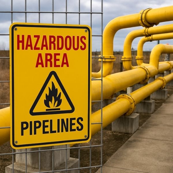
In industrial facilities where flammable gases, combustible dusts, or volatile chemicals are present, maintaining proper pipeline temperatures becomes a matter of life and death. Heat tracing systems serve as the unsung heroes of process safety, preventing catastrophic failures while ensuring operational continuity in the most challenging environments imaginable.
This comprehensive guide explores everything you need to know about implementing heat tracing solutions in hazardous areas, from fundamental principles to cutting-edge technologies that are revolutionizing industrial thermal management.
What is Heat Tracing? A Fundamental Overview
Heat tracing, also known as surface heating or pipe tracing, is a thermal management technique that applies controlled heat along the length of pipes, vessels, and equipment to maintain desired temperatures. This technology prevents:
- Freezing of water-based fluids
- Viscosity increase in heavy oils and chemicals
- Crystallization of process materials
- Condensation in gas lines
- Process temperature drops below critical thresholds
The Science Behind Heat Tracing
Heat tracing works on the principle of heat transfer compensation. As pipelines lose thermal energy to the surrounding environment, the tracing system continuously replenishes this lost heat, maintaining equilibrium at the target temperature.
The heat loss equation fundamental to system design is:
Q = U × A × ΔT
Where:
- Q = Heat loss (Watts)
- U = Overall heat transfer coefficient
- A = Surface area
- ΔT = Temperature difference between pipe and ambient
Understanding Hazardous Area Classifications
Before implementing any heat tracing solution in dangerous locations, understanding area classifications is paramount.
North American Classification (NEC/CEC)
| Class | Division 1 | Division 2 |
|---|---|---|
| Class I (Gases) | Ignitable concentrations exist continuously | Ignitable concentrations only during abnormal conditions |
| Class II (Dusts) | Combustible dust in suspension | Dust accumulations present but not normally suspended |
| Class III (Fibers) | Easily ignitable fibers handled | Fibers stored but not manufactured |
International Classification (IEC/ATEX)
| Zone | Description | Gas/Vapor | Dust |
|---|---|---|---|
| Zone 0/20 | Continuous presence | 1000+ hours/year | Continuous dust cloud |
| Zone 1/21 | Likely occurrence | 10-1000 hours/year | Occasional dust cloud |
| Zone 2/22 | Unlikely occurrence | <10 hours/year | Dust layers only |
Types of Heat Tracing Systems for Hazardous Locations
1. Self-Regulating Heat Cables
How They Work:
Self-regulating cables contain a conductive polymer core between two parallel bus wires. As temperature increases, the polymer expands, reducing electrical pathways and automatically decreasing heat output.
Advantages for Hazardous Areas:
- Cannot overheat even when overlapped
- Inherently safe design reduces ignition risk
- Automatic temperature adjustment without thermostats
- Cut-to-length installation flexibility
Ideal Applications:
- Freeze protection in Zone 2/Division 2 areas
- Process temperature maintenance up to 150°C
- Tank heating in chemical storage facilities
2. Constant Wattage (Parallel Resistance) Cables
How They Work:
These cables maintain consistent power output regardless of temperature, using heating zones connected in parallel across bus wires.
Advantages for Hazardous Areas:
- Higher temperature capabilities (up to 260°C)
- Predictable heat output for precise process control
- Field-cuttable to required lengths
Considerations:
- Requires more sophisticated control systems
- Potential overheating if installed improperly
3. Mineral Insulated (MI) Heat Tracing Cables
How They Work:
MI cables feature resistance heating elements surrounded by magnesium oxide insulation within a metal sheath (typically stainless steel, Inconel, or copper).
Advantages for Hazardous Areas:
- Extreme temperature capability (up to 600°C+)
- Exceptional mechanical durability
- Resistant to moisture, chemicals, and flame
- Longest service life (25+ years)
Ideal Applications:
- High-temperature process lines
- Critical safety systems
- Refineries and petrochemical plants
4. Impedance Heat Tracing
How They Work:
This system uses the pipe itself as the heating element by passing low-voltage AC current through it.
Advantages for Hazardous Areas:
- Highest power density available
- Uniform heat distribution
- No external heating elements to damage
Ideal Applications:
- Very long pipeline runs
- High-viscosity product transfer
- Emergency heating systems
5. Steam Tracing Systems
How They Work:
Small-diameter tubing carries steam alongside the main process pipe, transferring heat through conduction.
Advantages for Hazardous Areas:
- No electrical ignition sources
- Proven technology with decades of reliability
- Suitable for extremely hazardous Zone 0 locations
Disadvantages:
- Lower thermal efficiency
- Requires steam infrastructure
- More maintenance-intensive
Critical Components for Hazardous Area Heat Tracing
Explosion-Proof Connection Kits
All electrical connections in hazardous areas must use certified junction boxes and terminations rated for the specific zone classification.
Key Requirements:
- Flameproof enclosures (Ex d) for Zone 1
- Increased safety (Ex e) for Zone 2
- Intrinsic safety (Ex i) for Zone 0
- Proper cable glands with sealing compounds
Temperature Sensing and Control
Thermostat Options:
- Mechanical Thermostats – Simple, reliable, limited accuracy
- Electronic Controllers – Precise control, programmable setpoints
- RTD/Thermocouple Sensors – High accuracy for critical processes
- Skin-Sensing Technology – Measures actual pipe temperature
Power Distribution Panels
Hazardous area heat tracing requires specially designed power panels with:
- Ground fault protection (typically 30mA sensitivity)
- Circuit breakers sized for cable load
- Monitoring systems for cable integrity
- Emergency shutdown integration
Design Considerations for Hazardous Area Applications
1. Heat Loss Calculations
Accurate heat loss calculations form the foundation of any successful heat tracing design. Factors include:
- Pipe diameter and wall thickness
- Insulation type and thickness
- Ambient temperature extremes
- Wind exposure
- Maintenance temperature requirements
- Process fluid properties
2. Cable Selection Matrix
| Factor | Self-Regulating | Constant Wattage | Mineral Insulated |
|---|---|---|---|
| Max Maintain Temp | 150°C | 260°C | 600°C+ |
| Max Exposure Temp | 215°C | 260°C | 980°C |
| T-Rating | T3-T6 | T2-T6 | T1-T6 |
| Installation Complexity | Low | Medium | High |
| Initial Cost | $$ | $$ | $$$$ |
| Operating Cost | Low | Medium | Medium |
3. Thermal Insulation Requirements
Proper insulation is essential for:
- Energy efficiency – Reduces power consumption by 50-80%
- Temperature uniformity – Prevents hot spots and cold zones
- Personnel protection – Prevents burns from exposed surfaces
Recommended Insulation Types:
- Calcium silicate for high temperatures
- Mineral wool for general applications
- Cellular glass for cryogenic and moisture-prone areas
- Aerogel for space-constrained applications
Installation Best Practices for Hazardous Zones
Pre-Installation Planning
- Conduct thorough area classification survey
- Review all applicable certifications and standards
- Verify cable T-rating matches area requirements
- Prepare detailed installation drawings
- Train installation crews on hazardous area requirements
Cable Installation Guidelines
Spiral Wrapping Method:
- Used when pipe heat loss exceeds cable output
- Spiral pitch calculated to achieve required watts/meter
- Increases cable consumption by 20-100%
Straight Run Method:
- Single or multiple cables run parallel to pipe
- Most economical for standard applications
- Cables secured with heat-resistant tape or bands
Critical Installation Rules:
- Never exceed minimum bend radius
- Secure cables every 300mm on horizontal runs
- Use proper spacing at valves, flanges, and supports
- Install sensors at coldest expected location
- Complete continuity testing before energizing
Hazardous Area Specific Requirements
- Barrier glands at all zone transitions
- Potting compounds to prevent gas migration
- Flame-proof junction boxes with proper certification
- Grounding per local electrical codes
- Inspection windows for visual cable verification
Monitoring and Control Systems
Smart Heat Tracing Technology
Modern facilities increasingly adopt intelligent heat tracing management systems that provide:
Real-Time Monitoring:
- Cable temperature at multiple points
- Power consumption per circuit
- Ground fault current levels
- Insulation resistance trending
Predictive Maintenance:
- Algorithm-based failure prediction
- Degradation curve analysis
- Automated maintenance scheduling
- Historical performance comparison
Integration Capabilities:
- DCS/SCADA connectivity
- Modbus, Profibus, HART protocols
- Cloud-based remote monitoring
- Mobile device notifications
Control Strategies
1. Ambient Sensing Control
- Simple thermostat monitors air temperature
- Activates heating below setpoint
- Economical but less precise
2. Pipe Sensing Control
- Measures actual pipe wall temperature
- More accurate temperature maintenance
- Prevents over-heating
3. Proportional Control
- Adjusts power output continuously
- Optimal energy efficiency
- Higher initial investment
4. Self-Regulating (No External Control)
- Cable self-adjusts based on temperature
- Simplest installation
- No control hardware required
Compliance and Certification Standards
International Standards
| Standard | Scope | Application |
|---|---|---|
| IEC 60079 | Explosive atmospheres equipment | International |
| IEEE 515 | Heat tracing design and installation | North America |
| ATEX Directive 2014/34/EU | Equipment for explosive atmospheres | European Union |
| IECEx | International certification scheme | Global |
Testing and Certification Requirements
All heat tracing equipment for hazardous areas must undergo:
- Type testing – Laboratory verification of design
- Quality assurance – Manufacturing process audits
- Marking compliance – Proper labels and documentation
- Installation verification – Third-party inspection
Required Certifications by Zone
Zone 0/Division 1:
- Intrinsically safe (Ex ia) circuits only
- Special protection (Ex s) where approved
- Full third-party certification required
Zone 1/Division 1:
- Flameproof (Ex d) enclosures
- Increased safety (Ex e) components
- Intrinsically safe (Ex ib) circuits
Zone 2/Division 2:
- Non-sparking (Ex nA) equipment acceptable
- Energy-limited circuits
- Simplified certification process
Maintenance and Inspection Protocols
Routine Inspection Schedule
| Frequency | Inspection Activity |
|---|---|
| Daily | Visual check of control panel indicators |
| Weekly | Verify operating temperatures at key points |
| Monthly | Check ground fault protection operation |
| Quarterly | Insulation resistance testing |
| Annually | Complete system audit and thermographic survey |
Common Failure Modes and Prevention
1. Mechanical Damage
- Cause: Construction activities, vibration, thermal cycling
- Prevention: Physical protection, proper support spacing
- Detection: Visual inspection, continuity testing
2. Moisture Ingress
- Cause: Failed seals, damaged insulation, condensation
- Prevention: Proper sealing, weatherproofing, vapor barriers
- Detection: Insulation resistance testing, visual inspection
3. Overheating
- Cause: Blocked vents, insulation over cables, control failure
- Prevention: Proper design, T-rating verification, redundant controls
- Detection: Temperature monitoring, thermal imaging
4. Connection Failures
- Cause: Thermal cycling, corrosion, improper installation
- Prevention: Quality termination kits, proper training
- Detection: Resistance measurements, thermal imaging
Energy Efficiency Optimization
Strategies for Reducing Operating Costs
1. Insulation Optimization
Increasing insulation thickness from 50mm to 75mm can reduce heat loss by 25-30%, with typical payback periods of 1-3 years.
2. Smart Control Implementation
Weather-responsive controls that anticipate temperature changes can reduce energy consumption by 15-25% compared to simple thermostatic control.
3. Zone-Based Temperature Management
Different areas may require different maintenance temperatures. Proper zone design prevents over-heating low-temperature areas.
4. Off-Peak Operation
Where process permits, shifting heating loads to off-peak electricity periods can significantly reduce costs.
Energy Monitoring Best Practices
- Install power meters on all heat tracing circuits
- Track energy consumption trends over time
- Compare actual vs. calculated power requirements
- Investigate and correct variances promptly
Case Studies: Real-World Applications
Case Study 1: Offshore Oil Platform
Challenge: Maintain crude oil temperature at 65°C through 3km of exposed pipeline in Zone 1 environment with -20°C ambient conditions.
Solution:
- Self-regulating cables with T4 rating
- Stainless steel braid outer jacket for corrosion resistance
- Redundant cable installation on critical sections
- Remote monitoring via satellite uplink
Results:
- Zero freeze events in 7 years of operation
- 23% energy savings compared to constant wattage design
- Reduced maintenance visits to platform
Case Study 2: Chemical Processing Facility
Challenge: Prevent crystallization in caustic soda lines operating at 50°C in Zone 2 indoor environment.
Solution:
- Mineral insulated cables for maximum reliability
- Distributed temperature sensing for monitoring
- Integration with plant DCS system
- Predictive maintenance algorithms
Results:
- 99.98% system availability
- 40% reduction in unplanned maintenance
- Extended cable life beyond 20 years
Case Study 3: LNG Terminal
Challenge: Prevent ice formation on cryogenic valve actuators while maintaining intrinsic safety in Zone 1.
Solution:
- Intrinsically safe self-regulating cables
- IS barriers for all power feeds
- Low-power design within IS limits
- Redundant temperature monitoring
Results:
- Full compliance with LNG terminal safety requirements
- Reliable valve operation in all weather conditions
- Simplified permitting and inspection process
Emerging Technologies and Future Trends
Graphene-Enhanced Heat Cables
Research into graphene-based heating elements promises:
- Higher thermal conductivity
- Reduced weight per unit length
- Enhanced mechanical flexibility
- Potentially lower manufacturing costs
Wireless Monitoring Systems
Battery-powered wireless sensors are transforming heat tracing monitoring by:
- Eliminating sensor cable installations
- Enabling monitoring in previously inaccessible areas
- Reducing installation costs by 30-50%
- Supporting easy retrofit of existing systems
AI-Powered Predictive Analytics
Machine learning algorithms are being developed to:
- Predict cable failures months in advance
- Optimize energy consumption in real-time
- Automatically adjust setpoints based on process conditions
- Reduce maintenance costs through targeted interventions
Sustainable Heating Solutions
The industry is exploring:
- Solar-assisted heat tracing for remote locations
- Heat recovery integration from process waste heat
- Low-carbon electric heating powered by renewables
- Improved insulation materials with lower environmental impact
Frequently Asked Questions
Q1: Can heat tracing cables be used in Zone 0 environments?
A: Yes, but only intrinsically safe (Ex ia) circuits are permitted in Zone 0. This significantly limits power output and requires carefully designed systems with appropriate barriers and certification.
Q2: How long do hazardous area heat tracing systems typically last?
A: With proper installation and maintenance:
- Self-regulating cables: 10-20 years
- Constant wattage cables: 15-25 years
- Mineral insulated cables: 25-40+ years
Q3: What is T-rating and why does it matter?
A: T-rating (Temperature Class) indicates the maximum surface temperature a device can reach during operation. In hazardous areas, this must be below the auto-ignition temperature of gases or dusts present. Common ratings range from T1 (450°C max) to T6 (85°C max).
Q4: Can existing heat tracing systems be upgraded for hazardous area compliance?
A: Possibly, but it requires:
- Complete system assessment
- Replacement of non-certified components
- Possible cable replacement if T-rating is insufficient
- Recertification of the entire installation
Q5: How do I calculate the payback period for heat tracing investment?
A: Consider:
- Prevented production losses from freeze events
- Reduced maintenance and repair costs
- Energy savings from efficient design
- Extended equipment lifespan
- Avoided environmental incidents
Conclusion: Ensuring Safety and Reliability in Critical Applications
Implementing heat tracing systems in hazardous areas requires meticulous attention to design, component selection, installation practices, and ongoing maintenance. The consequences of failure extend beyond operational disruption to potential catastrophic events affecting personnel safety and environmental integrity.
Key takeaways for successful hazardous area heat tracing:
- Understand your hazard classification – Proper zone identification is the foundation of safe design
- Select appropriate technology – Match cable type to temperature, reliability, and certification requirements
- Invest in quality components – Certified equipment from reputable manufacturers reduces long-term risk
- Follow best practices – Proper installation and maintenance are as critical as design
- Embrace monitoring technology – Modern systems enable proactive management and optimization
- Plan for the future – Consider emerging technologies and sustainability requirements
By following these principles, industrial facilities can achieve the critical balance of safety, reliability, and efficiency that hazardous area heat tracing demands.
This article was created to provide comprehensive guidance on heat tracing solutions for hazardous area pipelines. For specific applications, always consult with certified engineers and follow applicable local codes and standards.