
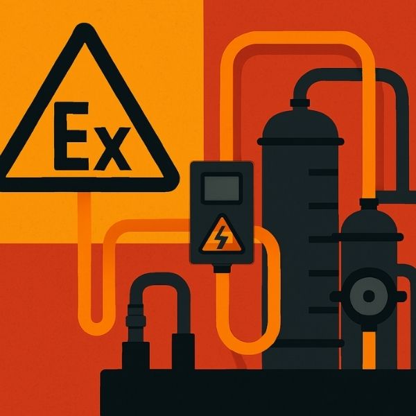
In industrial environments where flammable gases, vapors, combustible dust, or explosive atmospheres exist, the selection and installation of electrical cables become critical safety considerations. Hazardous area cabling differs significantly from standard electrical installations, requiring specialized specifications, rigorous testing, and precise installation methods to prevent catastrophic incidents. This comprehensive guide explores the essential aspects of cable systems designed for hazardous locations.
Understanding Hazardous Area Classifications
Zone Classification Systems
Hazardous areas are categorized based on the likelihood and duration of explosive atmosphere presence:
Gas and Vapor Environments:
- Zone 0: Explosive atmosphere present continuously or for extended periods
- Zone 1: Explosive atmosphere likely to occur during normal operations
- Zone 2: Explosive atmosphere unlikely, occurring only briefly if at all
Dust Environments:
- Zone 20: Combustible dust cloud present continuously
- Zone 21: Combustible dust cloud likely during normal operations
- Zone 22: Combustible dust cloud unlikely or brief occurrence
Temperature Classification
Cables must be rated for specific temperature classes (T1-T6) corresponding to the ignition temperature of surrounding materials, ranging from 450°C (T1) to 85°C (T6).
Critical Cable Specifications for Hazardous Areas
1. Cable Construction Requirements
Conductor Materials:
- High-purity copper or aluminum conductors
- Stranded construction for flexibility and durability
- Tinned copper for corrosion resistance in harsh environments
Insulation Materials:
- Cross-linked polyethylene (XLPE) for high-temperature resistance
- Ethylene propylene rubber (EPR) for chemical resistance
- Polyvinyl chloride (PVC) for cost-effective applications
- Fluoropolymers for extreme chemical exposure
2. Shielding and Armor Protection
Electromagnetic Shielding:
- Copper tape or wire braid shielding
- Aluminum-polymer composite shields
- Prevents electromagnetic interference in instrumentation circuits
Mechanical Protection:
- Steel wire armor (SWA) for physical impact resistance
- Galvanized steel for corrosion protection
- Stainless steel in highly corrosive environments
3. Flame Retardancy and Fire Performance
Hazardous area cables must meet stringent fire safety standards:
- Low smoke zero halogen (LSZH) compounds
- Flame propagation resistance per IEC 60332-3
- Fire survival capabilities for critical safety circuits
- Reduced toxic fume emission during combustion
International Standards and Certifications
Primary Regulatory Frameworks
IEC Standards:
- IEC 60079 series: Equipment for explosive atmospheres
- IEC 60092-353: Electrical installations in ships – cables for hazardous areas
- IEC 60331: Fire resistance testing
North American Standards:
- NEC Article 500-516: Hazardous classified locations
- UL 2225: Cables for hazardous locations
- CSA C22.2: Canadian electrical code requirements
ATEX Directive:
- European directive 2014/34/EU for equipment in explosive atmospheres
- Certification requirements for Ex-rated cables
Essential Certifications
- BASEEFA (British Approvals Service for Electrical Equipment)
- FM Approvals (Factory Mutual)
- IECEx certification scheme
- GOST-R for Russian markets
Installation Requirements and Best Practices
1. Cable Entry and Sealing Systems
Gland Selection:
- Certified Ex-rated cable glands matching zone classification
- Double compression glands for enhanced sealing
- EMC glands for electromagnetic compatibility
Sealing Requirements:
- Compound-filled seals to prevent gas migration
- Barrier seals between hazardous and safe areas
- Weatherproof sealing in outdoor installations
2. Cable Routing and Support
Physical Protection:
- Rigid conduit systems in high-risk zones
- Cable tray with continuous bonding
- Minimum bending radius: 12-15 times cable outer diameter
- Segregation from hot surfaces and mechanical hazards
Earth Bonding:
- Continuous earth connection throughout installation
- Armor bonding to earth at both ends
- Equipotential bonding in Zone 0/20 areas
- Earth resistance below 10 ohms
3. Termination and Connection Practices
Junction Box Requirements:
- Ex-certified enclosures matching area classification
- IP66 or higher ingress protection rating
- Flameproof (Ex d), increased safety (Ex e), or intrinsically safe (Ex i) design
Termination Methods:
- Compression lugs for reliable connections
- Proper cable stripping to prevent insulation damage
- Correct torque application per manufacturer specifications
- Maintenance of creepage and clearance distances
4. Documentation and Labeling
Essential Documentation:
- Cable schedules with zone classification
- Installation drawings showing routing
- Test certificates and compliance documents
- Maintenance and inspection records
Labeling Requirements:
- Cable identification tags at intervals
- Zone classification markers
- Voltage and current ratings
- Circuit identification
Cable Types for Specific Hazardous Applications
Power Distribution Cables
Medium Voltage (MV) Cables:
- 3.3kV to 33kV ratings for industrial distribution
- XLPE insulation with metallic screening
- Single or three-core configurations
- SWA protection with LSZH oversheath
Low Voltage (LV) Cables:
- 600V to 1000V applications
- Multi-core construction for motor circuits
- Flame-retardant compounds
- Flexible designs for moving equipment
Instrumentation and Control Cables
Intrinsically Safe Circuits:
- Blue sheath identification
- Individual pair screening
- Low capacitance design
- Certified for Ex ia/ib applications
Process Control Cables:
- 4-20mA signal transmission
- HART protocol compatibility
- Collective and individual screening options
- Moisture barrier protection
Specialized Applications
Thermocouple Cables:
- Mineral insulated (MI) construction
- Type K, J, T specifications
- Stainless steel sheath
- High-temperature operation up to 1000°C
Fiber Optic Cables:
- Non-electrical transmission for maximum safety
- Armored construction for mechanical protection
- EMI/RFI immunity
- High bandwidth for modern control systems
Testing and Quality Assurance
Factory Testing Requirements
Electrical Tests:
- Conductor resistance measurement
- Insulation resistance testing (minimum 100 MΩ)
- High voltage withstand test
- Partial discharge testing for MV cables
Mechanical Tests:
- Tensile and elongation testing
- Crush and impact resistance
- Bending cycle tests
- Armor wire pull-out force
Environmental Tests:
- Cold bend test (typically -40°C)
- Heat aging resistance
- Chemical immersion testing
- UV exposure resistance
Site Installation Testing
Pre-commissioning Tests:
- Continuity verification
- Insulation resistance (minimum values per voltage)
- Earth bond continuity
- Polarity and phase rotation
Documentation:
- Test certificates with recorded values
- Non-conformance reports
- As-built drawings
- Commissioning sign-off
Maintenance and Inspection Protocols
Regular Inspection Schedule
Visual Inspections (Quarterly):
- Cable support integrity
- Physical damage assessment
- Gland and seal condition
- Corrosion identification
Electrical Testing (Annual):
- Insulation resistance trending
- Earth continuity verification
- Thermal imaging for hot spots
- Partial discharge monitoring (MV cables)
Common Failure Modes and Prevention
Mechanical Damage:
- Implement physical barriers
- Regular route inspections
- Proper cable support spacing
- Impact protection in vulnerable areas
Environmental Degradation:
- UV-resistant oversheaths for outdoor installation
- Chemical-resistant materials selection
- Proper drainage to prevent water accumulation
- Temperature monitoring in extreme conditions
Electrical Stress:
- Avoid overloading circuits
- Monitor harmonics in VFD applications
- Maintain proper terminations
- Voltage surge protection
Cost Considerations and ROI Analysis
Initial Investment Factors
Cable Material Costs:
- Hazardous area cables typically 30-150% more expensive than standard cables
- Certification and testing overhead
- Specialized installation labor requirements
- Ex-rated accessories and components
Long-term Value:
- Extended service life (20-30 years typical)
- Reduced maintenance costs
- Minimized downtime from failures
- Liability protection and regulatory compliance
Cost Optimization Strategies
Design Phase:
- Optimize cable routes to minimize lengths
- Select appropriate specifications without over-engineering
- Consolidate cable types where possible
- Plan for future expansion
Procurement:
- Bulk purchasing for large projects
- Pre-qualified vendor lists
- Total cost of ownership analysis
- Quality vs. price balance
Emerging Technologies and Future Trends
Advanced Cable Materials
Nanotechnology Applications:
- Enhanced thermal conductivity
- Improved flame retardancy
- Superior mechanical properties
- Extended operational temperatures
Smart Cables:
- Integrated fiber optic monitoring
- Temperature sensing capabilities
- Partial discharge detection
- Predictive maintenance features
Installation Innovations
Pre-fabricated Systems:
- Factory-terminated cable assemblies
- Reduced installation time
- Consistent quality control
- Lower on-site labor costs
Digital Documentation:
- BIM (Building Information Modeling) integration
- QR code identification systems
- Cloud-based maintenance records
- Augmented reality installation guides
Case Study: Offshore Oil Platform Cable Installation
Project Overview
A North Sea oil platform required complete electrical infrastructure upgrade in Zone 1 and Zone 2 areas with exposure to saltwater, hydrocarbons, and extreme weather.
Solution Implemented
Cable Selection:
- MV cables: 11kV XLPE, SWA, LSZH for main distribution
- LV power: 0.6/1kV multi-core, armored, marine-grade
- Instrumentation: IS-rated, individually screened, blue sheath
- Fiber optic: Armored, gel-filled for communication systems
Installation Approach:
- Modular pre-fabricated cable assemblies
- Ex d junction boxes with redundant sealing
- Continuous earth bonding network
- Comprehensive testing protocol
Results
- Zero installation defects during commissioning
- 40% reduction in installation time vs. traditional methods
- Full compliance with ATEX and IECEx requirements
- Projected 25-year service life with minimal maintenance
Conclusion
Hazardous area cabling represents a critical intersection of electrical engineering, safety science, and regulatory compliance. Proper cable specification, installation, and maintenance in explosive atmospheres directly impacts personnel safety, operational continuity, and asset protection.
Success in hazardous location electrical installations requires:
- Thorough understanding of zone classifications
- Selection of appropriately certified cables and components
- Meticulous installation following best practices
- Comprehensive testing and documentation
- Ongoing maintenance and inspection programs
As industrial facilities continue to operate in increasingly challenging environments, the importance of properly specified and installed hazardous area cable systems cannot be overstated. Investment in quality materials, skilled installation, and regular maintenance provides substantial returns through enhanced safety, regulatory compliance, and operational reliability.
Organizations operating in hazardous environments should partner with qualified electrical contractors, maintain current knowledge of evolving standards, and prioritize safety above short-term cost considerations. The consequences of cable failure in explosive atmospheres extend far beyond equipment damage—they involve human lives and environmental protection.